All things Raspberry Pi and Time Lapse

Posts tagged ‘raspberry pi’

LED Notification Light Box

The Hypnocube was a great project and I am very happy with it. It is amazing to just turn on and watch it! But I was never able to figure out how to program it to my own custom animations. I have not used that programming language before, and it is quite complex! Then I stumbled across this great tutorial on Instructables where it is shown how to create a project that connects to Twitter and changes color based on the “mood” that it found. The main hardware is an arduino, a shield to connect to wifi, an RGB LED, and a frosted acrylic container. This seemed like a great project, but I decided that I would use it for gmail notifications and other ideas instead. Based on this tutorial here at Adafruit I already knew how to turn on and off the LED to accomplish this using a Rasbperry Pi. And instead of building my own acrylic box I bought this one from Amazon. It came clear, so I also bought some 400 grit sandpaper. By rubbing the sandpaper in a circular path, the box soon had that “frosted” look. The instructables project was where I got the idea on how to frost the acrylic. He was frosting the sheets of acrylic before he made the box, which would have been easier to do I am sure. The tight corners made it difficult to get it totally frosted in some places. But the advantage of my box is that it doesn’t have the glue in the corners. And since it was cheap I am happy with the route that I took. And after spending some time sanding I got all of the hard to get spots enough that it doesn’t show.

The Raspberry Pi has enough pins to individually control 7 normal LEDs. So for my project that means two RGB LED’s and one more regular LED. I put the two RGB LEDs side by side then added two more white LEDs on either side to form a diamond shape. Both white LEDs are controlled together, so they are both on or both off. However since the Raspberry Pi only has one PWM pin, I would only be able to get full values of each of the color. So for example RED would be on, while GREEN and BLUE were off. Or RED and GREEN were on, but BLUE was off. Or all three were on. But I would not be able to get a mixture of those, like RED being at 40% and GREEN at 90% and BLUE at 20%. However there is some software that makes that possible. It basically turns the full values on and off really fast to simulate PWM. The link for that code is here on GitHub. So now I will be able to make any mixture of those RGB values. It works great and is very simple to use.

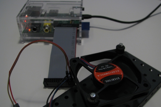
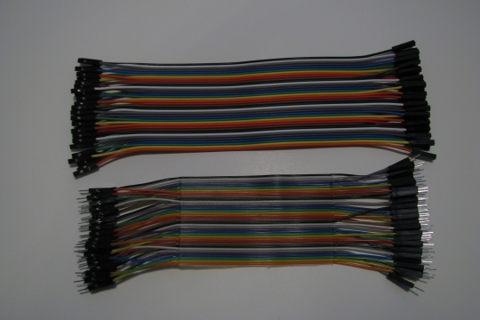
The next issue was the fact that my Adafruit breadboard wires are really short and that would look pretty terrible to have them all lose. And the LED box would have to be really close to the Raspberry Pi.  Then I thought about a regular network cable and did some research on the type of wire was used in them. Turns out it is very similar to the breadboard wires. So I ask on the Raspberry Pi forum if it would work to use a network cable instead of the short breadboard wires and was told that it should work just fine. Voltage drop was the only issue mentioned as a possible problem, but after measuring it, I can say that there was no voltage drop. A regular Cat5 network cable has 8 wires. And I would be using all of them. The six pins of the RGB LEDs and the one pin for the two white LEDs would use 7 wires. That left the 8th wire to be used for ground. I used a mini breadboard to handle the resistors and the connection to the Raspberry Pi and it works better than I thought it might! So now the LED box can be a few feet away from the Raspberry Pi.

After assembling everything in the box came the time for writing the code. I started with the example from Adafruit, but changed it to suit my LED setup. So now every 5 minutes the script check to see if there is an email, and if so it flashes red and white for about 30 seconds. Another script that I worked on was to get it to fade between the three main colors. That takes about a minute to make a full cycle through the colors and looks pretty amazing.

All of this was fun and awesome, but it had to be run from the command line. I decided to fix that. There is a great tutorial that explains how to install Lighttpd (A lightweight webserver) and PHP here. I just ignored the parts about MySQL as I do not need that right now. Once that was all setup and configured I wrote a simple basic webpage with a button for each of the main colors. I also added a button to turn it all off, and another to fade through all the colors – it calls the script that fades the colors . I accomplished this through a PHP page that executes the correct shell script. So now from any web enabled device that is connected to our wifi network, anyone can turn on the LED box easily and simply.

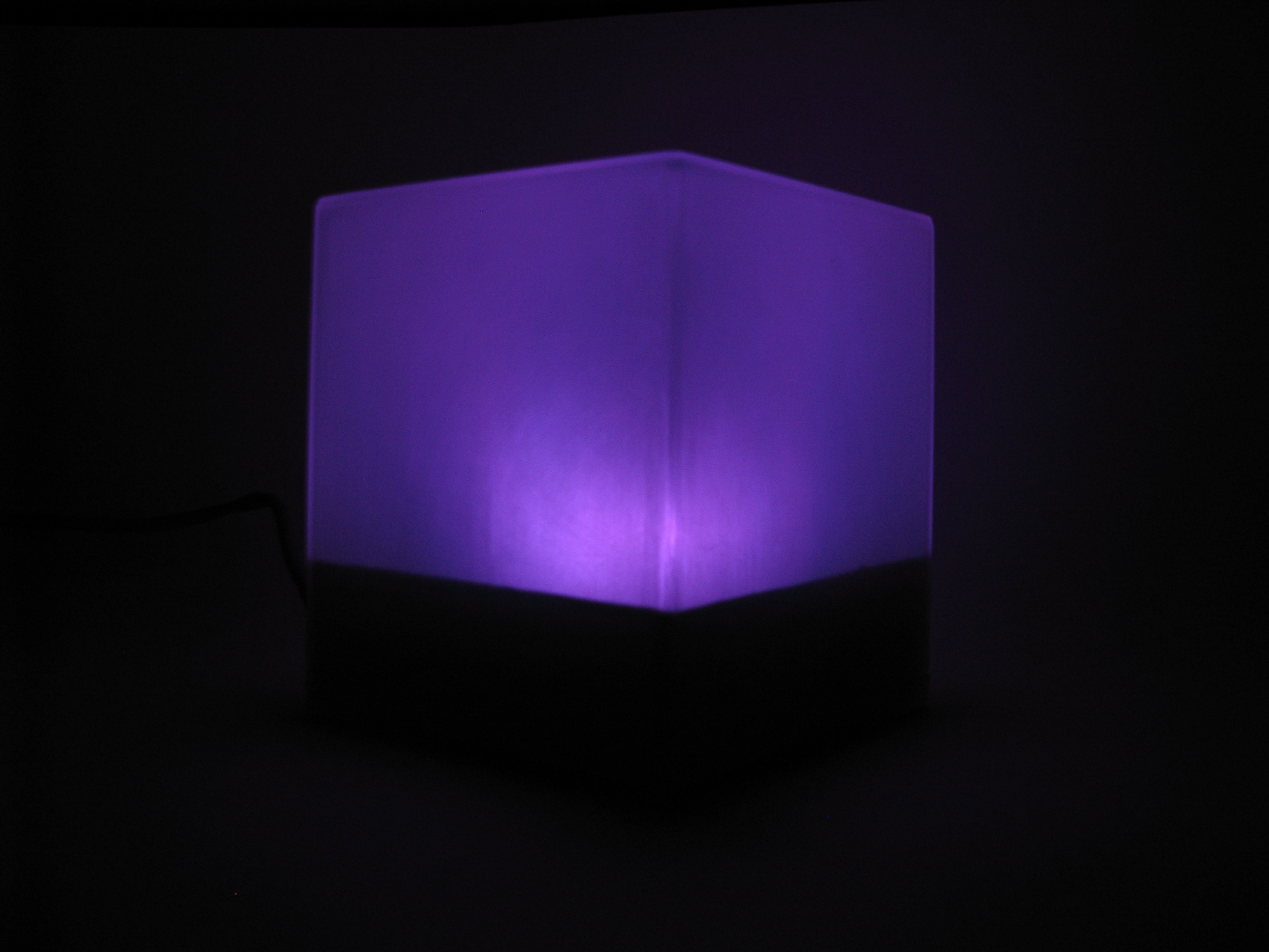
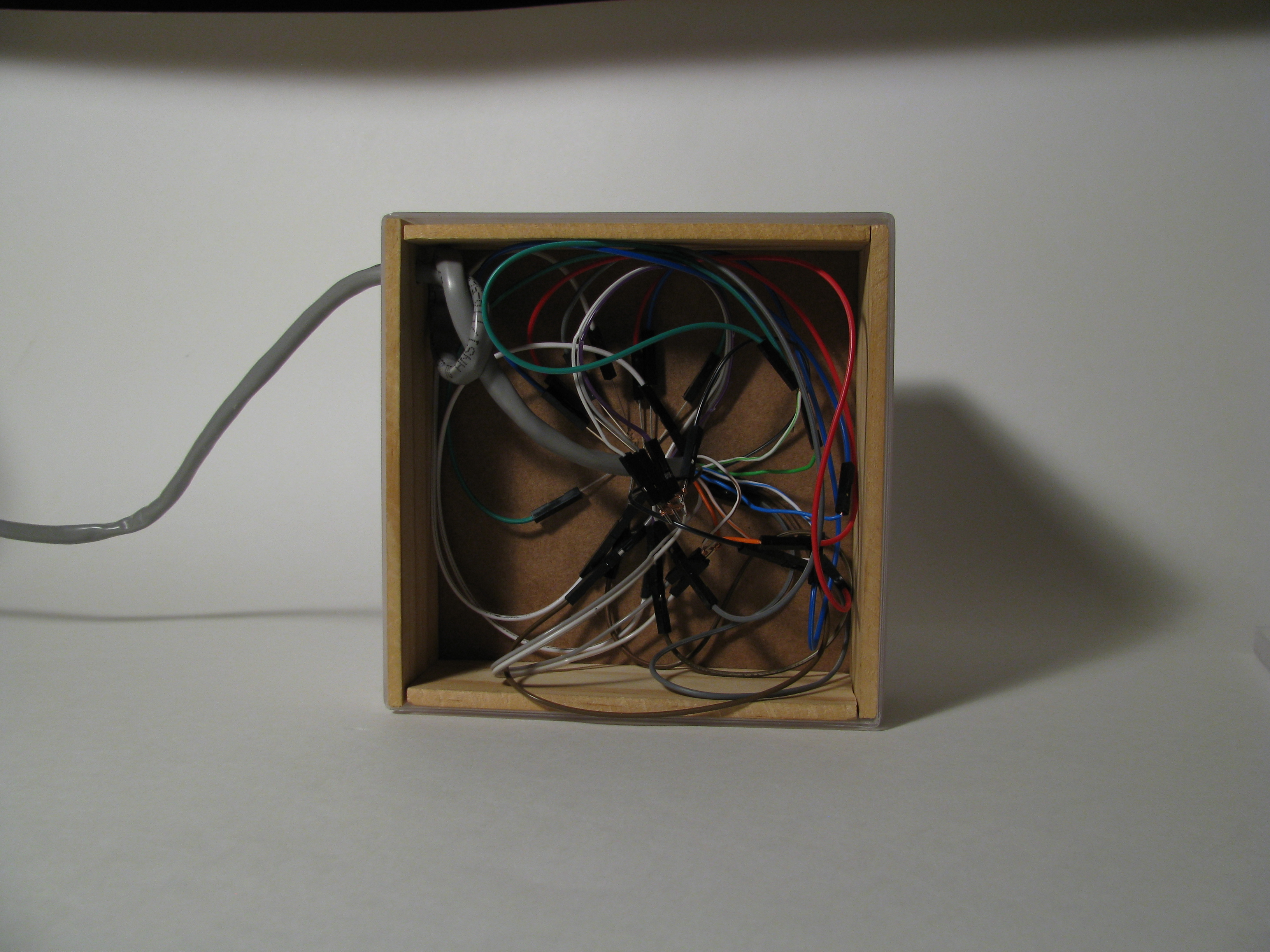
Below are some pictures showing how the box looks when lit different colors (no these are not just photoshopped to “show” the different colors) and the last one shows the wiring nightmare underneath!

IMG_9939 IMG_9943 IMG_9952 IMG_9953 IMG_9954 IMG_9955 IMG_9957 IMG_9960

And here is a quick screenshot of the web interface to control the LED box…

Screenshot_2013-03-18-22-26-15

Anyone have any other ideas for the LED light box?

Gertboard LED test scripts

I originally tested the Gertboard using the C code. But then when it came to modifying it I am not very familiar with C. So I downloaded the Python code available here from raspi.tv and it worked great! I was able to modify it and made some of my own visualizations and rewrote some of the current ones for the fun of it. The first couple are pretty basic. The last one shown in this video (about 0:52 seconds ) randomly chooses one of the LEDs and then creates two different “lives” on either side of that LED. Each time through the loop each life can move up or down. So one can move up and the other move down, or they might both move in the same direction. This continues until one of them tries to move to LED 0 or 13 which doesn’t exist, and then they die. But the other one continues until it also tries to move to 0 or 13. On the screen it prints out how many times it moved. Best I have seen using the LEDs is over 200. But just running the code on the computer without the delay I have seen over 640 moves without dying.

http://vimeo.com/58221381

Interesting and fun stuff!!

Finished and Uploaded!!

The video of the compilation of over 3 months is edited and uploaded! It has been 3 months since I setup the Canon PowerShot camera and Raspberry Pi in the greenhouse to watch the plants grow. And grow they did! The greenhouse starts out empty and in 15 seconds the plants are ceiling height. It was just under 90 frames total because some of the frames were too dark to use. And unfortunately some of the current images are pretty dark. But it worked!! And now I know what to change so that the images are not as dark for next time. Let me know what you think in the comments!

https://vimeo.com/57635944


Now I am looking at setting up for a year – as was my original goal…


GPIO Computer Case Fan and LED Cube

My 5V computer case fan arrived and I was very interested to see if I could power it from the Raspberry Pi. So I turned everything off, and plugged it into the GPIO cable. I had put the case back together with this cable because that makes it easy to access the GPIO. I went to fan manufacture and found that the Red wire was 5V input, the Black wire was ground, and the Blue wire was for the frequency readings. So I used some of the recent F/F jumper cables and plugged GPIO pin 1 into the Red for power and GPIO pin 3 into the black for power. Powered the Raspberry Pi on and right away the fan started up! Success! Now to go on and figure out a way to leave it plugged in and via software be able to control when the fan powers up. And possibly try to get the Blue wire working as well.

This site http://elinux.org/RPi_Low-level_peripherals has a diagram of the GPIO pins.

First picture is the Raspberry Pi powered off… Hard to see, but the fan blades are stopped.

IMG_0928_edited

Next two shots are powered and show the lights on the Raspberry Pi and the fan is a blur.

IMG_0930_edited IMG_0936_editedAnd the next is the jumpers that came from Adafruit…IMG_0937_edited

I stumbled across this site today http://hypnocube.com/ and was wondering about a Raspberry Pi controlled version…. They have a kit to buy that is currently $150 for the 4x4x4 cube. Sounds as if custom programming is limited to minimal so that is a bummer. There is a video here of someone who has done this with a Raspberry Pi. His notes about it are here. And there are some videos of people running it off an Arduino. Here is the youtube link to a demonstration of some of the things an 8x8x8 cube (blue) can display. This video and others from the same channel showing what the cube can do are amazing! A tutorial can be found here on a 4x4x4 cube using an arduino.

Pandora Internet Radio – In a portable box

Great tutorial here on Instructables on how to build a portable Internet radio box. This project includes some soldering, but has good instructions. I am going to look into installing pianobar as that looks like it could be really useful and right at home on the Rasberry Pi.

Sparkfun Electronics

I was sitting around today wishing that my Gertboard was here… But its not. One of the things I am planning on doing is messing around with temperature and humidity sensors. It is possible to do this without a Gertboard, but I would like to have that hardware experience before I try anything directly on the GPIO pins. There is a very good forum discussion on the Raspberrypi site here.

There is a temperature sensor and a humidity sensor on SparkFun that look like they would work. There is also a waterproof temperature sensor on SparkFun as well. These sensors are different in that some are a 1 wire interface and others are a 2 wire interface. These sensors would be extremely helpful for the case of a timelapse camera. The current case turns the heater on at a certain temperature and the fan on at a certain temperature. This works, but I cannot change/edit that temperature. One of the major problems is humidity, especially in a greenhouse environment. If I could control the fan I could have the fan cycle every X minutes no matter what the temperature.

Currently when I need to download the pictures from the timelapse project I plug in the Ethernet cable. This works, but would not work for the v2.0 case. I am thinking of building a case similar to these here. However these cases are very expensive, and do not offer much flexibility for a Raspberry Pi and other electronics. And so I would need another way to connect to the Raspberry Pi. As mentioned on this forum/article the Edimax adapter looks like it is a good choice.

Hoping to have some more pictures, maybe a short timelapse of the project so far up soon!

Aside

Raspberry Pi case for test Pi

I recently bought a second Raspberry Pi to experiment with (and hopefully connect to a gertboard) while the original Raspberry Pi is taking pictures. And I decided to buy a case for this one. And in this post I am talking about a real case, as in a case meant for a Raspberry Pi and not  a security camera like my other Raspberry Pi is housed in. After lots of searching I finally found a case I liked, but it had bad reviews. So I decided against that one. I really liked the clear case idea because hiding the Raspberry Pi in a colored case seemed pointless. Then I found Built-toSpec’s case and I really liked it – except it was black or a somewhat transparent purple. On his website it mentioned that his custom laser services offered clear acrylic so I contacted him and ask how much it would cost for a clear version of the Raspberry Pi case. Turns out he had already made some that were clear. So I ordered a clear one and it arrived really fast. It took awhile to put together because of having to peel all of the protective layers off, but it went fast after that. It is held together by 4 screws in the ends and fits together nicely. It has slots in the top for the expansion pins and a slot for a GPIO cable.

The gertboard is supposedly being shipped by Newark. However, it was supposed to ship around the end of November, then that changed to first of November, and now it is back to end of November. So maybe by the end of the year I will have one… Hopefully…

Below are pictures of the Raspberry Pi in the case.

ImageImageImageImageImageImageImageImage

Everything is accessible, but the Pi is still nicely protected. And it is clear and study. This case is awesome!

Back up and running

It is all setup again – as of Saturday – and should be taking pictures. Here is a shot of what it looks like now. All of the tomato plants have been removed and the new ones will be planted soon.

Something that started to concern me was Daylight Savings time. This would be a problem if the camera changed time and then the power went out. The raspberry pi would pull the new time and it would be an hour off of what it was before. I contacted Canon about this potential issue. And they tried to sell me one of their newer cameras that has this feature. But they said that the Canon Powershot A510 does not have this feature. I could not find this option on the SX100 either. However this is a good thing as it means I am safe from having to worry about that. It will definitely be something to think about in the future however.

I changed the way the scripts were written and so I will post them and the updated crontab hopefully sometime early next week.

Problem Solved!

I now know what the problem with the time lapse setup was. For some reason Canon decided to put every like 100 pictures into a new folders and name the folders 157CANON and 158CANON and so on. So it was leaving these pictures on the camera card and not downloading them onto my card. This causes a problem because the card (in the camera) filled up and then it stopped taking pictures. That makes sense why it wont take a picture when the card is full, but it doesn’t make sense why Canon operates this way. However this is the easy part of the problem. The harder part was getting it to take a picture again. I would reformat the SD card using the cameras reformat option and then try to take a picture from gphoto2. It would give an “unspecified error” and that was not very helpful in figuring out the problem. The solution (which took me forever to figure out) was that the first picture has to be physically taken from the camera. After that first picture is taken by actually pushing the physical button on the camera, then gphoto2 will take pictures just fine.

So the solution is to make sure that I take that first picture and then make sure that the SD card does not fill up. This is possible to achieve from gphoto2 because it is possible to naviagate into the sd card that is in the camera by issueing the command

gphoto2 –shell

and then some* of the regular linux commands work. I say * because very few work and those that do have minor quirks. The main command “cd” works like normal, but there are some issues with tab completion. I wrote this script that uses a here document to actually execute the commands. This was the only way I could figure out how to get it to work. This script is not finalized because I think I will actually want to save the pictures that it is leaving in this folder until I can be certain that it is downloading the same picture onto the Raspberry Pi. (UPDATE) I setup and let it shoot for a day as a test and I confirmed that it is starting a new folder every 100 pictures. And it is NOT saving a copy of it to the Raspberry Pi. It takes the 100th picture and leaves it on the card. And leaves it in the terrible naming format as well.

#!/bin/bash
# jamesmiller
To be updated….

Hopefully going to install the project back in the greenhouse this weekend!!

Update… And its not good…

I went to check on how the time lapse setup was working. And it was not. It worked for not quite a week and then stopped taking pictures for some reason. So I brought it home and have been working to see what was wrong. And so far I cant figure it out. I cannot get the camera to take a picture using gphoto2 anymore. I tried a whole new installation of Arch (I kept the previous one separate) and it still wont take a picture. The other camera that I had bought previously (Canon Powershot SX100) will work just fine though. So that would lead me to believe that the Powershot A510 wont work. However, the camera will still take a picture just fine when it is disconnected from the Raspberry Pi and functioning like a regular camera.

So now I am not sure what to try. It seems like it is a problem with the camera, but the camera will still take a picture so it didnt completely die. Anyone have any suggestions?

Tag Cloud